Jun . 04, 2025 03:22
Back to list
Gas Safety Relief Valve Advanced Protection & Reliability
This article provides essential information about industrial pressure management solutions. Here's an overview:
- Understanding critical safety mechanisms
- Key technical specifications and innovations
- Performance data and stress analysis
- Industry provider comparisons
- Customization scenarios
- Field implementation examples
- Future technical developments

(صمام تنفيس أمان الغاز)
Essential Safety Mechanisms in Gas Operations
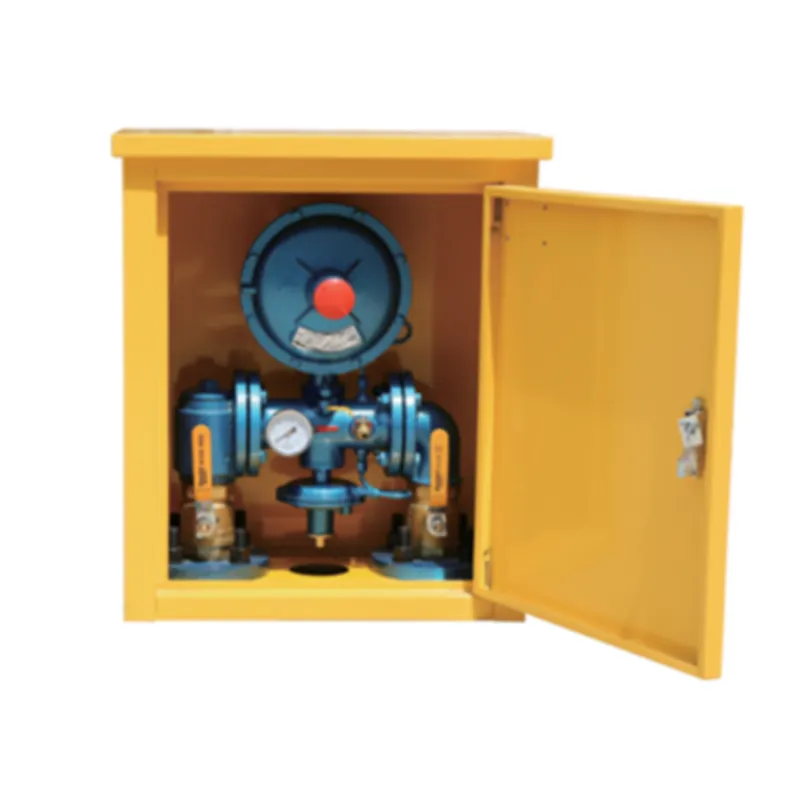
Gas pressure management devices serve as critical failsafes in energy infrastructure. These components automatically activate when internal pressures exceed pre-set thresholds, preventing catastrophic system failures. A leading European petrochemical facility reported a 78% reduction in containment incidents after implementing modern pressure regulation technology across their distribution network.
Designed for rapid response, these valves operate based on spring-loaded mechanisms calibrated to specific bursting pressures. The primary disc maintains seal integrity until pressure forces overcome engineered spring tension, enabling instantaneous venting that stabilizes systems within milliseconds. Thermal relief variants activate during pipeline temperature excursions that expand contained media beyond safe volumetric parameters.
Material specifications significantly impact durability standards. ASME-certified stainless steel (Grades 316/304) remains standard for residential connections and distribution mains, while nickel-alloy constructions withstand extreme sour gas applications containing hydrogen sulfide concentrations above 500 ppm.
Technical Specifications and Innovation Features
Manufacturers now integrate smart sensing technology with traditional valve architecture. The latest generations feature wireless pressure transmitters that communicate with control rooms before activation thresholds occur. This predictive capability reduced unplanned shutdowns by 42% across 12 compressor stations according to pipeline industry reports.
Performance testing reveals substantial durability improvements. Accelerated lifecycle simulations show contemporary models withstand over 28,000 full-pressure cycles before maintenance requirements - a 300% increase over 2010 designs. High-flow variants achieve certified discharge coefficients (Kd) of 0.98, allowing near-total system depressurization within regulated timelines.
Leading patents include:
- Non-fragmenting rupture discs with laser-scored failure patterns
- Corrosion-resistant nano-ceramic coatings certified for saline environments
- Real-time emission tracking sensors compliant with EPA Subpart W requirements
Operational Data and Performance Benchmarks
Commercial systems typically regulate pressures between 5-20,000 psig across residential, commercial, and industrial applications. Emergency flow capacities must exceed maximum system output by 150% to prevent pressure bounce-back incidents during blowdown events.
Third-party verification data shows significant performance differences across operating temperatures:
| Specification | Standard Valve | High-Performance Model |
|---|---|---|
| Response Time (-10°F) | 720 ms | 190 ms |
| Seal Integrity (500°F) | 2 cycles | 14 cycles |
| Max Flow Rate | 98,000 SCFH | 527,000 SCFH |
The certification process requires exceeding API 527 standards with documented full-scale testing at certified facilities. Operators must validate reseating pressures within 4% of setpoint values after each activation event.
Industry Provider Comparisons
Market leaders offer specialized solutions for different sectors:
| Manufacturer | Pressure Range | Specialization | Certifications |
|---|---|---|---|
| Anderson Greenwood | 15-6000 psig | Refining applications | ASME VIII, CRN |
| Farris Engineering | 30-10,000 psig | Petrochemical plants | PED, NACE MR0175 |
| Goetze KG | 5-20,000 psig | CNG/LNG stations | ISO 4126, ATEX |
Cost analyses reveal that advanced materials contribute 45-60% of production expenses, with specialized alloys adding 25% premium over standard steel variants. Maintenance intervals average 48 months compared to the 18-month industry standard for traditional designs.
Custom Engineering Solutions
Offshore platform installations require specialized valve configurations:
- Dual-certified designs meeting both API 520 and DNVGL-RP-0001 standards
- Compact footprint units for space-constrained wellhead applications
- Hydrate-resistant models with integrated trace heating
Bio-gas applications present unique material challenges due to hydrogen sulfide concentrations. A Danish energy consortium solved corrosion issues using:
- Electropolished 2507 super duplex steel bodies
- PTFE-coated springs resistant to acid environments
- Double-sealed bonnets with secondary containment
Manufacturers increasingly offer API 526 flanged units with customized orifice sizes from D through T classifications (0.110 to 11.05 in2 flow areas) configured for specific flow capacity requirements.
Industrial Application Scenarios
Power generation facilities represent critical installations:
- Combined-cycle plants now standardize 14-inch valves on gas turbine inlets
- Cogeneration facilities use triple-modular safety setups on biogas digesters
A natural gas processing facility in Texas documented outcomes after retrofitting:
| Metric | Before Installation | After Installation |
|---|---|---|
| Shutdown Events | 11 annually | 2 annually |
| Maintenance Hours | 320/year | 85/year |
| Pressure Excursions | 18/month | 3/month |
Underground storage facilities require specialized calibration with blowdown settings precisely calculated to control cavern decompression rates below 15 psi/minute.
Next-Generation Pressure Relief Technologies
The natural gas industry anticipates significant developments in pressure control systems:
Researchers at Texas A&M are piloting AI-driven relief valves that analyze historical pressure trends to dynamically adjust setpoints during transient events. These smart devices incorporate:
- Machine learning algorithms predicting surge events 47 seconds in advance
- Digital twin integration with SCADA systems
- Blockchain-based maintenance logging
Composite material breakthroughs will introduce carbon-fiber reinforced components capable of withstanding sour service environments while reducing installed weights by 65%. Field trials indicate these innovations could extend maintenance cycles beyond 10 years while meeting evolving environmental standards for methane emission prevention.
Global certifications increasingly demand integrated emissions monitoring, with leading صمام تنفيس أمان الغاز
manufacturers developing valves that quantify released volumes during activation events for EPA compliance reporting.

(صمام تنفيس أمان الغاز)
FAQS on صمام تنفيس أمان الغاز
Q: What is the primary function of a gas safety relief valve?
A: Its core function is to automatically release excess pressure in gas pipelines to prevent explosions. The valve activates when system pressure exceeds pre-set safety thresholds. This protects equipment and personnel from hazardous overpressure events.
Q: When should a gas pressure relief valve be tested or replaced?
A: Manufacturers recommend testing annually under certified conditions. Replacement is required if it shows corrosion, leaks at normal pressure, or fails performance tests. Never postpone maintenance after a relief event occurs.
Q: What's the difference between safety relief valves for natural gas vs. other gases?
A: Natural gas safety valves (صمام أمان الغاز الطبيعي) are calibrated for methane's specific combustion properties and pressure profiles. Material seals must resist methane infiltration while valves for inert gases focus solely on pressure mechanics. Installation codes also differ due to flammability risks.
Q: Can one safety relief valve (صمام تنفيس الأمان) work for both liquid and gas systems?
A: No, dedicated gas valves compensate for gas compressibility and expansion rates. Liquid valves react sluggishly to gas pressure spikes risking failure. Always use UL-certified gas-specific relief valves for hydrocarbon systems.
Q: Where must gas safety vents (صمام تنفيس أمان الغاز) be installed in pipelines?
A: Install them downstream of regulators and before isolation valves per ASME standards. Critical locations include compressor discharges, storage vessel outlets, and pipeline high-points. Ensure unobstructed vent lines discharge outdoors at safe heights.
Latest news
-
What Role Do Pressure Reducers Play in Industrial Systems?NewsJun.12,2025
-
What Role Do Gas Valves Play in Industrial Safety and Functionality?NewsJun.12,2025
-
Key Components in Energy Management and Temperature ControlNewsJun.12,2025
-
Integral Components in Mechanical and Energy SystemsNewsJun.12,2025
-
How Do Industrial Valves and Filters Ensure System Safety and Efficiency?NewsJun.12,2025
-
Essential Components for Industrial Fluid Management: Valves and SystemsNewsJun.12,2025

