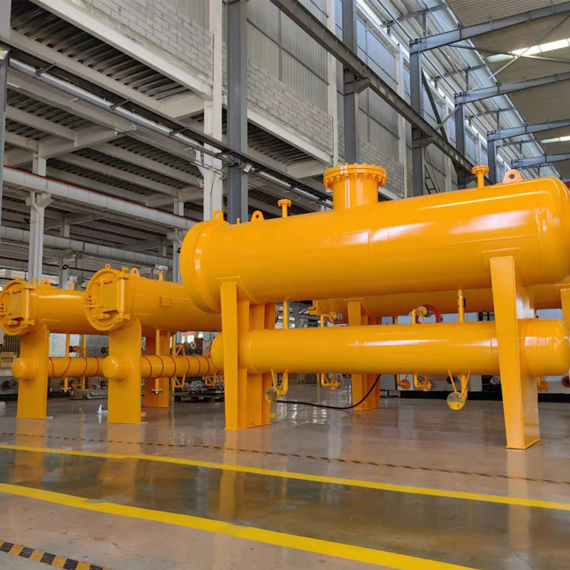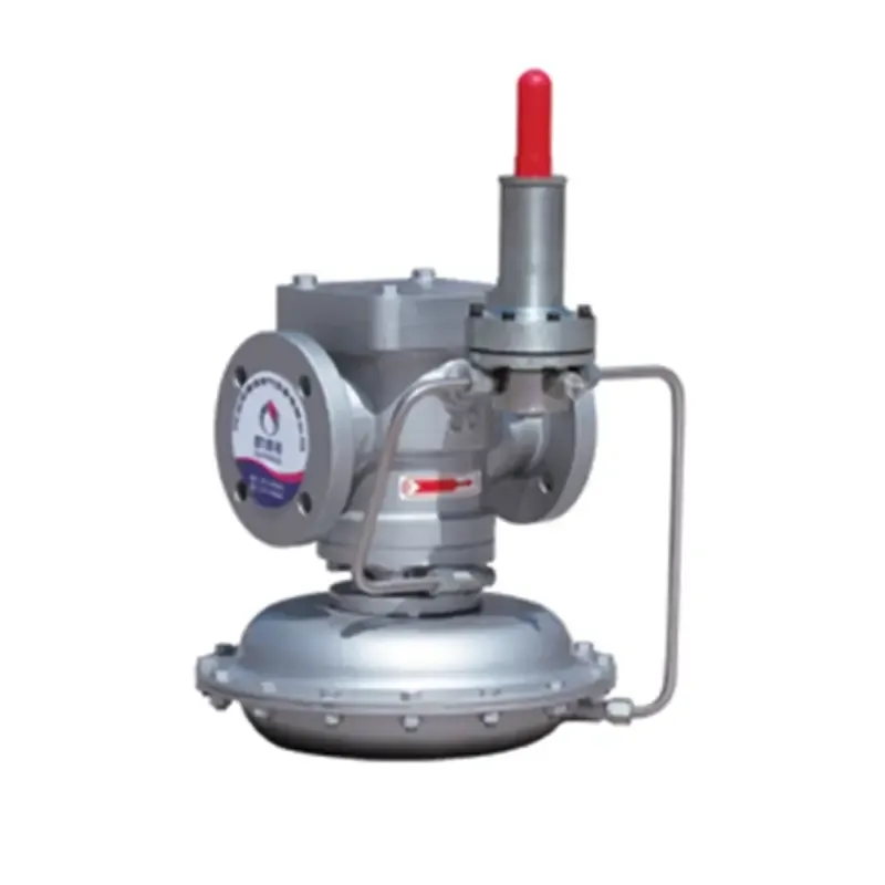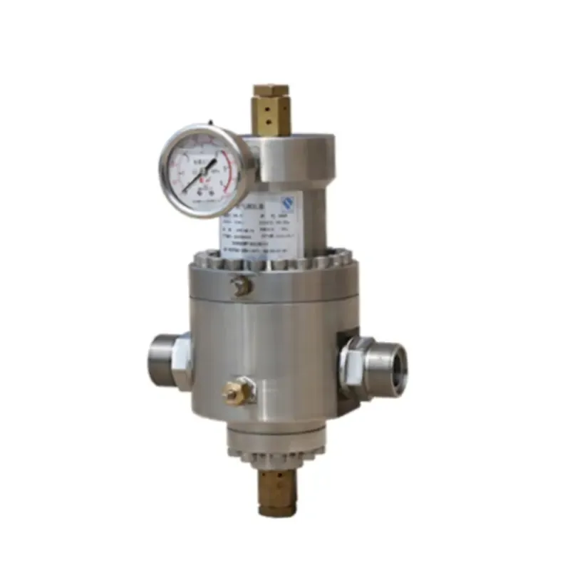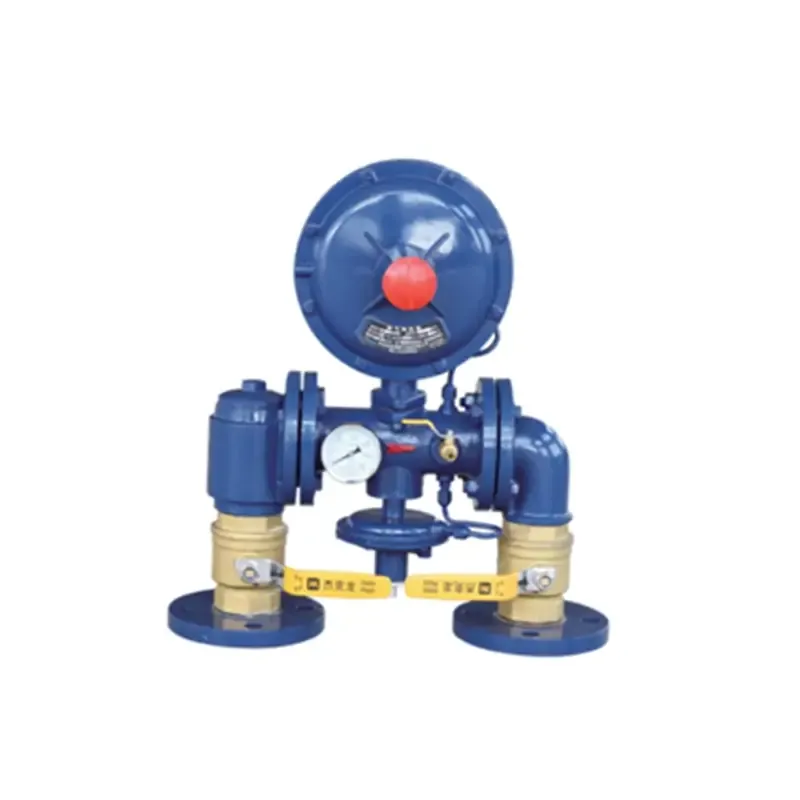
A natural gas filter separator is two-stage filtering equipment for half fine filtration and fine filtration of natural gas through the mechanism of centrifugal separation, foam capture by screen and cohesion intercept and is also an efficient purification device for removal of solid and liquid impurities in the gas. It has high purification efficiency, large dust holding capacity, stable operation and low investment and operation cost and is simple and easy to install and use.
It is applicable to natural gas, city gas, mine gas, liquefied petroleum gas, air and other gases.
A gas containing solid particles and droplets enters into the filter separator, and the gas such as natural gas is subject to primary filtration through a filter element to filter solid particles and condense droplets.
Due to the structural feature of the filter element, the solid particles are filtered or absorbed by the filter element, and one part of gaseous mist liquid is condensed into large droplets to enter a liquid trap chamber. The gas subject to first filtration flows to a mist separation chamber, the rest gaseous mist liquid constantly condenses on the inner surface of a mist catcher to form large droplets which are separated from the gas by gravity. The filtered gas such as natural gas is discharged out of the chamber through an outlet to complete secondary filtering.
Design standard: GB 150.1 ~ 150.4-2011 Pressure vessels, HG/T20582-2011 Specification for stress calculation of steel chemical vessels
Structure: vertical, horizontal
End cover type: Fast-opening type, flange cover type
Connecting flange standard: HG/T20592 ~ 20635-2009 or ANSI B16.5, etc.
Filter element material: Polyester fiber
Design pressure: <10 MPa
Design temperature: -40°C~+90°C
Initial differential pressure: ≤0.02 MPa
Filtering separation accuracy and efficiency
Solid: ≤1 μm99%
Liquid: ≤5 μm98%
Filtering separation accuracy rating: 0.3 μm, 1 μm, 3 μm, 5 μm, 10 μm, 20 μm and 50 μm
Used for filtration and separation of natural gas, city gas, mine gas, liquefied petroleum gas and air; used for removal of desiccant particles and droplets at downstream of a drying bed; used for removal catalyst powder and droplets at downstream of a catalyst bed; used for gas filtration and separation in front of metering stations, gate stations and pressure regulating stations; and used for gas filtration and separation of urban gas distribution system.
Used for filtration and separation of natural gas, city gas, mine gas, liquefied petroleum gas and air; used for removal of desiccant particles and droplets at downstream of a drying bed; used for removal catalyst powder and droplets at downstream of a catalyst bed; used for gas filtration and separation in front of metering stations, gate stations and pressure regulating stations; and used for gas filtration and separation of urban gas distribution system.
Structure form
K type, F type
K type - fast-opening type
F type - flange cover type
Mounting form
V type, H type
V type - vertical mounting
H type - horizontal mounting
Specification interpretation
Example: DN250/DN100 - main cylinder diameter is DN250, and the inlet and outlet diameter is DN100
The filter separator includes horizontal mounting and vertical mounting. During horizontal mounting, the levelness of main axis of the equipment is less than 5/1000. During vertical mounting, the non-perpendicularity of main axis of the equipment is less than 3/1000. The equipment is connected through flanges and provided with a vent valve, a safety valve, a pointer type differential pressure gauge, a level meter and a pressure gauge.
|
Structure Size Table of FH Type and KH Type Filters |
|||||||||||||||||||
|
Filter specifications |
Structure size (mm) |
Nominal size of nozzle |
|||||||||||||||||
|
L |
L1 |
L2 |
L3 |
L4 |
L5 |
L6 |
L7 |
L8 |
H |
D1 |
D2 |
1 |
2.5 |
3 |
4.6 |
78 |
9-12 |
13.14 |
|
|
DN300/DN100 |
2400 |
1650 |
150 |
200 |
200 |
300 |
250 |
200 |
300 |
700 |
250 |
100 |
15 |
32 |
40 |
100 |
32 |
100 |
15 |
|
DN300/DN150 |
2400 |
1700 |
150 |
200 |
200 |
300 |
250 |
200 |
300 |
700 |
300 |
150 |
15 |
40 |
40 |
150 |
40 |
150 |
15 |
|
DM350/DN200 |
2900 |
1800 |
200 |
200 |
200 |
300 |
250 |
200 |
400 |
700 |
350 |
150 |
15 |
40 |
50 |
200 |
40 |
200 |
15 |
|
DN400/DM250 |
2900 |
2000 |
200 |
200 |
200 |
350 |
250 |
200 |
400 |
800 |
400 |
200 |
15 |
40 |
50 |
250 |
40 |
250 |
15 |
|
DN450/DN250 |
3600 |
2100 |
200 |
200 |
200 |
350 |
250 |
200 |
500 |
800 |
450 |
200 |
15 |
40 |
50 |
250 |
40 |
250 |
15 |
|
DN500/DN300 |
3800 |
2100 |
200 |
200 |
200 |
350 |
250 |
200 |
600 |
800 |
500 |
250 |
15 |
40 |
50 |
300 |
40 |
300 |
15 |
|
DN600/DN300 |
2400 |
2200 |
200 |
250 |
250 |
350 |
300 |
250 |
600 |
800 |
600 |
250 |
15 |
40 |
50 |
350 |
40 |
350 |
15 |
|
DN700/DN350 |
2400 |
2200 |
200 |
250 |
250 |
400 |
300 |
250 |
700 |
900 |
700 |
250 |
15 |
50 |
80 |
350 |
50 |
350 |
15 |
|
DN800/DN400 |
2400 |
2400 |
250 |
250 |
250 |
400 |
300 |
250 |
700 |
900 |
800 |
300 |
15 |
50 |
80 |
400 |
50 |
400 |
15 |
|
DN900/DN400 |
2900 |
2400 |
250 |
300 |
300 |
400 |
350 |
250 |
800 |
900 |
900 |
300 |
15 |
50 |
80 |
400 |
50 |
400 |
15 |
|
DN1000/DN400 |
2900 |
2450 |
250 |
300 |
300 |
400 |
350 |
300 |
800 |
1000 |
1000 |
350 |
15 |
50 |
100 |
400 |
50 |
400 |
15 |
|
DN1200/DN400 |
2900 |
2450 |
250 |
300 |
300 |
400 |
350 |
300 |
800 |
1000 |
1200 |
400 |
15 |
50 |
100 |
400 |
50 |
400 |
15 |

